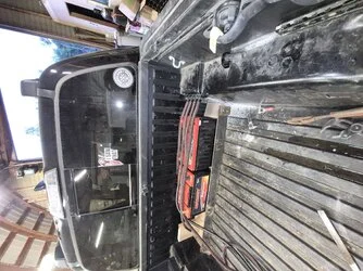

In the world of high-fidelity mobile audio, the difference between a championship-level system and a potential fire hazard often comes down to the integrity of the electrical infrastructure. Recently, a technical inquiry regarding the proper fusing for a dual-amplifier setup—specifically utilizing the Rockford Fosgate Prime R2 series—has sparked a broader discussion among enthusiasts and installers. The core of the issue involves managing a 1200.1 mono block and a 500×4 multichannel amplifier, while simultaneously integrating a secondary battery for enhanced current stability.
This article examines the technical requirements for powering high-wattage audio systems, the physics of circuit protection, and the industry-standard protocols for installing auxiliary power sources.
The Foundation of Circuit Protection: Why Fusing Matters
The primary function of a fuse in a vehicle’s 12-volt electrical system is not to protect the audio equipment, but rather to protect the vehicle itself. A fuse is a sacrificial safety device designed to melt and break the circuit in the event of an electrical short or an over-current condition. Without adequate protection, a short circuit in a high-gauge power cable can draw hundreds of amps from the battery instantly, heating the copper wire to the point of melting its insulation and potentially igniting the vehicle’s carpet or dashboard.
When a user questions why manufacturer-recommended fuse ratings seem "high," they are often grappling with the distinction between average current draw and peak current demand. Amplifiers are dynamic loads; their power consumption fluctuates wildly based on the impedance of the speakers and the musical content being played.
Technical Analysis of the Rockford Fosgate Prime Setup
In the case of the Rockford Fosgate Prime R2 1200.1 and the R2-500X4, the manufacturer provides specific baseline recommendations: 200 Amps for the monoblock and 80 Amps for the four-channel amplifier.
The Peak Demand Reality
The R2 1200.1 is engineered to deliver substantial power to subwoofers, which are the most power-hungry components in any audio chain. Low-frequency reproduction requires massive current bursts. If an installer ignores the manufacturer’s 200A recommendation in favor of a smaller fuse, the system will likely experience "nuisance blowing," where the fuse snaps during a heavy bass transient, even though the wire is perfectly capable of handling the load.
Conversely, the R2-500X4 handles mid and high-frequency speakers, which are generally more efficient. An 80A rating for this unit provides ample headroom for the amplifier to operate at its full dynamic range without thermal or electrical clipping.
Chronology of Installation Best Practices
To ensure a safe and efficient installation, professionals generally follow a structured approach to power distribution.
Phase 1: Cable Selection and Ampacity
Before choosing a fuse, one must choose the wire. The 0 AWG (American Wire Gauge) cable is the industry gold standard for high-wattage trunk installations. Copper, being highly conductive, allows for minimal voltage drop over the length of the vehicle. However, the "ampacity" of 0 AWG wire—its ability to carry current safely—is limited by its physical thickness and thermal dissipation. Most high-quality oxygen-free copper (OFC) 0 AWG cables are rated for approximately 250 to 300 Amps.
Phase 2: The Main Distribution Block
When running two amplifiers, the standard practice is to run a single, heavy-gauge "main" power cable from the engine bay battery to a distribution block in the trunk. This main cable must be fused within 18 inches of the primary battery. The rating of this main fuse should reflect the sum of the individual amplifier demands, provided that the rating does not exceed the maximum ampacity of the main cable.
Phase 3: Secondary Battery Integration
The addition of a secondary battery (often an AGM or Lithium-iron phosphate unit) changes the electrical topography. The second battery serves as a "buffer," providing a reservoir of current closer to the amplifiers. This reduces the strain on the vehicle’s alternator and the long run of power wire from the front of the car.
Supporting Data: Calculating Total Current Draw
When calculating the aggregate fuse requirement for the Rockford Fosgate setup, we use the principle of additive load:
- R2 1200.1: 200 Amps (Peak)
- R2 500X4: 80 Amps (Peak)
- Total Potential Demand: 280 Amps
If an installer utilizes a 300A main fuse, they are effectively protecting the 0 AWG wire from a dead short while allowing the system to access its full 280A peak potential. It is a common misconception that the fuse "pushes" power to the amp; in reality, the amplifier "pulls" power, and the fuse simply acts as a gatekeeper.
Official Industry Responses and Safety Standards
Most manufacturers, including Rockford Fosgate, emphasize that their fuse recommendations are based on "worst-case scenario" testing. If a user installs a smaller fuse than recommended, they risk the amplifier starving for current during high-volume playback, which can actually cause more heat build-up inside the amplifier’s internal power supply—potentially leading to equipment failure.
The American Boat and Yacht Council (ABYC) and various automotive electrical engineering standards suggest that circuit protection should be rated at no more than 125% of the expected continuous load. However, in mobile audio, because music is transient, installers often deviate slightly from this, prioritizing the prevention of "nuisance trips" while strictly adhering to the wire’s thermal melting point.
Implications of Improper Fusing
The implications of failing to fuse correctly are twofold:
- Under-fusing: Leads to system shutdowns, blown fuses at inopportune times, and potential damage to the amplifier’s internal components due to voltage instability.
- Over-fusing: This is the most dangerous scenario. If an installer uses a 400A or 500A fuse on a cable that can only handle 250A, the wire will become the "fuse." In the event of a short, the wire insulation will melt, smoke, and potentially catch fire before the fuse ever triggers.
The Role of the Secondary Battery Fuse
A critical point often missed by novice installers is the necessity of fusing the connection between the primary and secondary battery. The cable connecting the two batteries is essentially a live wire running through the vehicle. If the car is in a collision and that cable is pinched against the chassis, the energy stored in both batteries will discharge instantly. Therefore, it is standard practice to place a fuse at the exit of the primary battery and another fuse at the entry of the secondary battery.
Conclusion: A Balanced Approach
For the Rockford Fosgate Prime R2 1200.1 and 500×4 setup, the math is clear:
- Use high-quality 0 AWG copper wire.
- Implement a 300A main fuse at the primary battery.
- Distribute power through a fused distribution block, using 200A for the monoblock and 80A for the 4-channel.
- Ensure the secondary battery is fused on both the positive input and the positive output to the amps to maintain a "safety loop."
By adhering to these principles, the enthusiast not only protects their financial investment in audio hardware but ensures the longevity and safety of the vehicle itself. Audio performance is ultimately tethered to electrical reliability; when the power foundation is solid, the music will follow suit with clarity and impact. Always prioritize high-quality connections, tight mechanical crimps, and appropriately rated hardware to ensure that your mobile audio system remains a source of joy rather than a source of danger.