In the nuanced world of high-end audio engineering and vintage vacuum tube restoration, few challenges are as persistent as the optimization of driver stages. Recently, a technical discourse emerged within the audiophile community—centered on the application of the RE084 vacuum tube—that highlights the delicate balance between theoretical design and practical operating constraints. The discussion, which brings together the expertise of seasoned engineers and simulation hobbyists, underscores the necessity of rigorous modeling when pushing historical components beyond their intended parameters.
The Core Technical Challenge: The RE084 Paradox
The central point of contention in this ongoing engineering dialogue concerns the use of the RE084 vacuum tube as a driver within an amplification circuit. While the RE084 is celebrated for its specific sonic characteristics, it is a component defined by strict physical limits.
The primary concern raised by experts in the field involves the relationship between input voltage and anode potential. The RE084 is rated for a maximum anode voltage (Va) of 150V. In professional tube circuit design, the "anode voltage" refers strictly to the potential difference between the anode and the cathode. To operate the RE084 within its linear region while maintaining longevity, engineers generally suggest a target anode voltage of approximately 140V or lower.
At this operating point, the grid bias (-Ug) typically sits near -3V, with an associated anode current of approximately 5 to 6mA. This creates a narrow "operating window." If an input transformer with a 1:4 ratio is utilized, the system risks overdriving the grid. A 1:4 ratio significantly amplifies the signal reaching the tube; even with a modest input, the resulting voltage swing can quickly exceed the tube’s safety threshold, leading to distortion or, in extreme cases, premature component failure.
Chronology of the Engineering Discourse
The dialogue, which gained momentum in late April 2024, began with a query regarding the RS282 and its interaction with Output Transformers (OPT). As the conversation progressed, the focus shifted toward the RE084 driver stage, specifically regarding the sufficiency of Henry (Hy) ratings in the inductive load.
- Initial Inquiry (April 25, 2024): A user queried the mathematical necessity of inductive reactance (Xl) relative to plate resistance (Rp). The discussion questioned the industry standard of setting Xl to 4 or 5 times the Rp, asking whether such a high ratio is strictly necessary or if lower ratios could be viable.
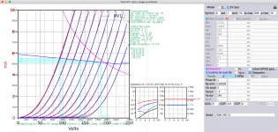
- The Simulation Phase: Technical contributors intervened, moving the conversation from theoretical heuristics to simulation-based evidence. Using the "Bartola MuTracer"—a sophisticated tool for characterizing vacuum tube behavior—engineers generated a comprehensive model of the RE084.
- Data Validation: By modeling the tube with a 250k load line (representing a gyrator or high-impedance load), participants were able to visualize the precise plate curves and identify the exact points where the RE084 would reach its limit of linearity.
Supporting Data: The MuTracer Simulation
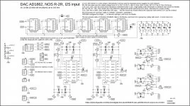
The integration of the Bartola MuTracer data serves as the backbone for the current consensus on the RE084. The simulation provided a detailed SPICE (Simulation Program with Integrated Circuit Emphasis) model, which allows engineers to predict how the tube will behave under various load conditions.
Key Parameters Extracted from the Model:
- Mu (Amplification Factor): 15.82
- Internal Plate Resistance (Rp): 250,000 Ohms
- Operating Point (Qui): Vp = 140V, Vg = -3V
- Capacitance Metrics: The model accounted for critical inter-electrode capacitances, including grid-to-cathode (CCG), grid-to-plate (CGP), and cathode-to-plate (CCP), which are essential for calculating high-frequency roll-off and stability.
The SPICE model provided, which includes the E1 and G1 voltage-controlled sources, offers a robust framework for those attempting to integrate the RE084 into modern designs. It specifically addresses the "positive grid current" phenomenon—a common pitfall where the grid acts as a diode, drawing current and distorting the signal when the input voltage exceeds the bias voltage.
Addressing the "Rule of Thumb": Why 4x or 5x?
A significant portion of the discourse focused on the common engineering mantra: The inductive reactance (Xl) should be 4 to 5 times the plate resistance (Rp).
The questioning of this rule is emblematic of a shift toward evidence-based design. In the case of the RE084, where the Rp is high (250k Ohms), achieving a 5x multiplier for Xl at 20Hz requires an immense inductance. Specifically:
- Calculation: Xl = 2 PI 20Hz * L.
- Requirement: To meet the 5x rule, one would need an inductance (L) of approximately 110 Henries.
Critics of the "blind" application of this rule argue that in specific modern designs—particularly those utilizing active loads or gyrators—the impedance can be artificially boosted. Therefore, the traditional Xl = 5Rp requirement may be a relic of transformer-coupled design rather than a universal law of vacuum tube electronics. If the load is sufficiently high-impedance, the frequency response can remain flat without requiring the physically massive transformers that would otherwise be needed to provide 110+ Henries of inductance.
Official Responses and Peer Review
The consensus among the contributors involved in the April 2024 analysis is that the RE084, while an excellent component, requires a "gentler" input stage than some designers might expect. The official stance of the community participants is summarized as follows:
- Voltage Management: Avoid high-ratio input transformers (such as 1:4) if the source signal is robust. A lower ratio or an active buffer stage is recommended to keep the input below the 6Vp-p limit.
- Load Line Selection: When using a gyrator or a high-impedance anode load, one must ensure that the DC operating point is strictly maintained at the 140V threshold to avoid exceeding the 150V anode maximum.
- Modeling over Heuristics: The community strongly encourages the use of the provided SPICE model over "rules of thumb." By calculating the specific load line for a given project, builders can avoid the distortion that occurs when the RE084 enters the non-linear region of its curve.
Implications for High-Fidelity Audio
The implications of this technical discourse are twofold. First, for the hobbyist, it serves as a cautionary tale regarding the misuse of vintage components. Without proper simulation, the RE084 is easily pushed into distortion, which many might erroneously attribute to the tube’s "character" rather than a failure of the surrounding circuit design.
Second, the discourse highlights a maturing of the DIY audio community. The reliance on the Bartola MuTracer data suggests that the community is moving away from "black box" engineering—where circuits are built based on intuition—toward a rigorous, data-driven approach that rivals professional laboratory standards.
As the industry continues to revisit historical vacuum tubes, the integration of SPICE modeling and precise characterization tools will become increasingly essential. The RE084 case study proves that even simple tubes can present complex engineering hurdles, and that the intersection of historical components and modern simulation provides the most reliable path toward high-fidelity sound reproduction.
For those looking to implement the RE084 in future projects, the technical takeaway is clear: respect the 150V anode limit, carefully calculate the input transformer ratio to prevent grid clipping, and always verify the operating point with a reliable SPICE model before committing to a final build. In doing so, the unique, liquid sound of the RE084 can be preserved and safely enjoyed within the parameters of modern high-end audio architecture.